35KV Class Three Phase Oil-Immersed Distribution Transformer Jiangsu Huayu Electric Co., Ltd , https://www.huayutransformer.com
Introduction
Trisun New A/C Compressor Evaluation Tester for Types of Compressor and Valve (CETM)
Model NO.: CETM
HS Code: 90262090
Model NO.: CETM
HS Code: 90262090
2018 Upgrade - A/C Testing with New Software System
The A/C Compressor Evaluation Test Machine (CETM) is designed to evaluate compressors without requiring the operator to have in-depth knowledge of their design or functionality. The 2017 updated CETM is built for compressor manufacturers and remanufacturers, offering greater automation and enhanced capabilities. It simulates the loads that a compressor would experience in a real vehicle air conditioning system.
The CETM requires a computer equipped with TDS Compressor Evaluation Software (TCES).
The software includes a list of common compressor models for convenience, but it can also test any compressor as long as you know its pulley diameter and displacement per revolution. You don’t need to know whether it's a fixed or variable displacement model—the machine automatically identifies the type and runs the appropriate test.
Quick Start
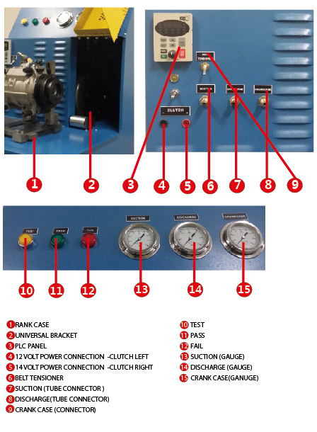
Using the CETM is straightforward. First, mount the compressor on the universal bracket and align it with the pulley, ensuring the belt is straight. The compressor should be properly oiled, and excess oil should be drained. Make sure all hoses are connected correctly. While measuring the crankcase pressure is not required, it can help with diagnostics.
Start the program and confirm that the machine is communicating with the computer. This is indicated by the status color on the DL405 PLC Communications panel changing from red to green.
The software consists of three main screens:
Variable Animation Screen – This screen provides an inside view of a generic variable displacement compressor. When the left animation is active, the compressor is running at minimum displacement. When the right animation is active, it’s running at full displacement. The bottom of the screen displays real-time pressure inputs.
Setup Screen – This screen shows the calibration settings, which are factory-set and should not be changed. The test duration is also set at the factory. The drive motor on the CETM can operate in both forward and reverse directions, though most compressors run forward.
The easiest way to run a test is to use the drop-down list in the "Select Compressor Type" field to choose a model that closely matches the one being tested. Select the model and click "OK."
It is possible to create a custom list that automatically populates the report page or printout. Use the text file provided by TDS and modify it to create your own. The file is named TheList.txt and located in C:/TDS/. Open it in a text editor like Notepad to add or remove models. Ensure the format is correct, and the last line must be "None,0,0,0,0."
Here is a sample format:
10PA20,2000,MyPartNumber,10PA20HX234,Denso
First,150,Part1,Model1,Mfg1
Two,160,Part2,Model2,Mfg2
Three,1700,Part3,Model3,Mfg3
None,0,0,0,0
For example, the first line could represent a 10PA20 compressor. The line would read: 10PA20,2000,MyPartNumber,10PA20HX234,Denso
Note: If it's a fixed displacement compressor, the displacement per revolution is multiplied by 10.
Once the Custom List is loaded, the default list will be unavailable until the program restarts. Add the Custom List by clicking the button next to the drop-down list.
Performance Report Screen – After selecting the compressor type, go to the Performance Report screen and enter the compressor clutch diameter in millimeters. Then ensure the compressor is properly aligned using the universal test bracket.
Press the start button. Once the test is complete, press the print button on the Setup screen to generate the report and save the data to disk.
Theory of Operation
A car air conditioning compressor functions as a pump designed to move gas through a closed system. There are many types and sizes of compressors. For the CETM to test various models, the system must be programmable to produce consistent results within a specified range. This is done by entering the displacement per revolution and the pulley diameter on the Performance Report screen. Using this data, the drive motor speed is adjusted to match the compressor size.
As mentioned earlier, the test mimics the loads experienced by a compressor in a real vehicle system. When the test starts, current is sent to an air pressure transducer that adjusts the suction pressure to approximately 3 bar. This is well above the pressure that would cause an evaporator to freeze and also simulates a medium to high heat load. If the compressor is a variable displacement model, the internal mechanical control valve should be set at the factory to match the crankcase pressure with the suction pressure.
The suction pressure is then reduced to simulate a low heat load or freezing evaporator temperature. If it's a variable compressor, the discharge pressure should drop significantly to unload the compressor. The suction pressure is then increased back to the high load condition, and the discharge pressure should rise again. For fixed displacement compressors, the discharge pressure drops proportionally with the suction pressure.
The discharge pressure is increased by adding a restriction in the discharge line. This is achieved using an adjustable orifice inside a metering valve. The pressure drop across the orifice is directly proportional to the mass flow rate. When the compressor reaches minimum displacement, the mass flow rate decreases. Upon shipment, the metering valve is set to a fixed orifice size to achieve the desired maximum discharge pressure. All compressors should reach similar maximum pressures at their peak output. This pressure can be adjusted using the metering valve, but it is recommended not to change it unless necessary.
Note: Adjusting this valve may require modifying the "Peak" setting located at the bottom right corner of the Performance Report screen.
The "Peak" setting represents the maximum pressure differential a good baseline compressor can achieve. Setting it too low may allow poorly performing compressors to pass, while setting it too high may cause good ones to fail. This setting is crucial, so careful adjustment is essential before making any changes.
The CETM features a frequency inverter that controls the drive motor speed. This inverter also sends power usage data to the computer during testing. Excessive power consumption can lead to poor motor durability.