Our company was set up in 2002.We are using the advanced cold punch technology to produce spark plug which is similar to NGK and Champion technology.With such technology, the metal shell and ceramic are better protected the quality of the spark plug are more stable to get avoid from air leaking and broken.Our spark plug products are ranged into more than 100 models with an anual out put of 6 million pcs. Besides the advanced technology,we also have a strong advantage of automatical production.Most of our production device is automatical that we have very high,efficiency and stable quality.Throughout such years of developing,we have gained a good reputation at domestic motorcycle manufacturer.Furthermore,our products have been exported to South East Asia, Middle East, Australia and so on. Revolution,refine and devotion are our principal of working.Welcome to visit us and raise your demand and your comments request are our target to strive. Motorbike Spark Plugs,Moto Normal Spark Plug,Bike Normal Spark Plug,High Quality Normal Spark Plug LIXIN INDUSTRIAL & TRADE CO.,Limited , https://www.jmpowerplugs.com
With the development of society, various water heaters and hot water pipelines have entered thousands of households. The requirements for water temperature on various occasions are varied, and it is often necessary to mix hot and cold water to the required temperature. It can control the water outlet temperature of various water heaters and pipeline hot water, and can quickly and accurately modulate the hot water of the required temperature. It can be used in showers, toilets and other water temperature intelligent preparation valves that require constant temperature and hot water, which is of practical value. technology. This design is in line with this need, with PIC16C71 as the core, controlling the mechanical part to automatically adjust the mixing ratio of cold water and hot water to achieve automatic control of the outlet water temperature and solve the problem caused by water pressure fluctuations, water temperature changes or changes in the water output. The water temperature is hot and cold, and there are obvious water-saving effects than manually adjusting the water temperature.
1 system structure and working principle Hot water and tap water as the two input control valve, the use of mixing valve to control the amount of cold and hot water input and proportion, mixed water outflow through the outlet for users to use. The temperature sensor installed at the outlet senses the temperature at the outlet and transmits it to the microcontroller through the temperature measurement circuit. The composition of the thermostatic water valve is shown in FIG. When the water outlet switch is turned on, the single chip compares the temperature at the water outlet measured by the temperature sensor with the set temperature. When needed, the PIC16C71 controls the DC motor to drive the mixing valve to adjust the proportion of cold and hot water entering the water valve. In order to control the temperature of the water, when the motor turns to the head, the MCU gets the corresponding signal and stops the motor from rotating in the same direction. Press the temperature rise or temperature drop button to set the water temperature in the range of 25~50°C. The LED digital display shows the set water temperature value. If the set temperature is different from the temperature detected by the sensor, according to the temperature difference between the two, the single-chip microcomputer outputs pulse voltage signals of different widths to control the DC motor to rotate at different speeds. The cold and hot water mixing valve is driven by the transmission mechanism to change cold water and hot water. The inflow ratio. When the external conditions change again, such as the water pressure decreases or increases, the temperature difference between the water temperature of the outlet pipe and the set temperature occurs. At this time, the SCM controls the motor rotation again, automatically adjusts the water temperature, and automatically adjusts the water temperature at the outlet. Keep the water temperature constant. 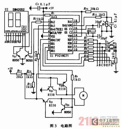

FIG. 3 is a circuit diagram of a control valve. The system uses a low voltage DC power supply and uses a PIC16C71 microcontroller to control it. The functions are implemented through program control. 
2.1 Principle of temperature measurement and parameter selection In Fig. 3, the thermistor RT is a temperature measuring element for measuring the water temperature at the outlet. A fixed resistor R16 is connected in series with the thermal RT to form a voltage divider circuit. The voltage drop across RT is connected to the built-in 8-bit A/D converter whose pin is connected to AN0 through the resistor R17 and the analog voltage signal is converted to digital. Signal, read by the program to achieve temperature measurement. The key to temperature measurement is to choose the right temperature measurement element and reasonable circuit parameters. Here is a negative temperature coefficient thermistor (NTC), which is packaged in a glass bulb, small size, low price, and easy to install. The main advantages of NTC thermistors are their large temperature coefficient of resistance, high sensitivity, and fast response. They enable precise temperature measurements. The main drawback is the non-linearity of thermoelectric characteristics. If C408503 (25°C, resistance 50kΩ, B value 4050K, glass encapsulation) NTC thermistor, in the range of 0~99°C, the sensitivity of the resistance is about 8500~100Ω/°C, and the nonlinearity is serious. Linear compensation is required. Here, through calculation, reasonable temperature measurement circuit parameters are selected. Within the effective temperature measurement range, linear compensation is not performed. The use of a temperature look-up table alone effectively solves the nonlinear problem of NTC temperature measurement resistance. The following discusses the selection of temperature measurement accuracy and circuit parameters.
Resistor R16 and the thermistor RT in series to form a voltage divider circuit, the power supply voltage 5V voltage divider, RT pressure drop Vi = 5V RT / (RT + R16) changes with temperature changes. This voltage is input to the A/D converter inside the PIC16C71 through the A/D input pin AN0, converted into a digital signal, and read by the program. Connect a 0.1μF capacitor C3 to RT for filtering to eliminate interference and noise. In the trial, it was found that when the selected NTC thermistor (such as the nominal value of 10kΩ) and the voltage divider resistance (such as 5.1kΩ) of the resistance is small, the thermistor is easily broken down after a period of work, and in With the use of NTC thermistors with higher resistance and voltage divider resistors, the problem is better resolved. The reason for the analysis should be the thermal breakdown caused by the large operating current and power dissipation in the NTC thermistor. Therefore, try to use a NTC thermistor with a higher resistance and a voltage divider resistor to minimize the current flowing through the thermistor. On the other hand, considering that the input leakage current of the A/D input signal pin of the PIC microcontroller is a maximum of ±500nA, to ensure the correct A/D conversion result, it is required that the voltage on the source resistance of the loss cannot exceed 10mV (A The /D reference voltage is 1/2 LSB at 5V. This requires that the internal resistance of the signal source should not exceed 20kΩ. When using an NTC thermistor nominally 50kΩ and B25/50 is 4050K, the resistance in the temperature range (0~99°C) varies between 168.3 and 3.217kΩ. When selecting a fixed voltage divider resistance of 20kΩ, the equivalent internal resistance of the A/D input signal source is the resistance value of the thermistor and the voltage divider resistor in parallel. The resistance range is 17.9 to 2.77kΩ, which can satisfy the A/D. During the conversion, the internal resistance of the signal source should not exceed 20kΩ, and the corresponding signal input voltage to the A/D must range from 4.469 to 0.693V, covering the effective A/D input voltage range (0 to 5V). Most of the digits after the 8-bit A/D conversion are between 0xE5 and 0x23. In the temperature range of 0-97°C, when the temperature changes by 1°C, the corresponding input voltage variation is between 55.5 and 19.7mV. All analog voltages greater than 1LSB correspond to 19.6mV, so the accuracy of ±8°C after 8 bit A/D conversion is guaranteed; between 97°C and 99°C. When the temperature changes by 1°C, the corresponding analog input voltage varies between 18.8 to 18.5mV, and the 8-bit A/D conversion temperature measurement accuracy does not reach ±1°C, but the normal temperature measurement is generally not higher than 95°C. And outlet temperature is controlled at 25 ~ 50 °C is also relatively low.
The above analysis shows that the conditioning circuit without the input signal can meet the temperature measurement accuracy of ±1°C. The A/D analog input pin AN0 is connected in series with R17 for current limiting protection to prevent chip damage or hardware deadlock caused by overvoltage input, as it will directly affect the internal resistance and sampling of the A/D analog input source. At time, the resistance of R17 cannot be too large, and the resistance value is chosen as 1k-Ω. RT uses NTC thermistor's precision is 50kΩ±0.5%, its B25/50 is 4050K±1%, the voltage divider resistor R16 selects the metal film resistor with good thermal stability, the precision is 20kΩ±0.5%.
2.2 Keyboard input and output display circuit design The PORTB port of the PIC16C71 is used to control the input circuit and has a weak pull-up circuit with software control. The keyboard query circuit consists of resistors R6, R7, R8, buttons S1, S2, S3, and resistor R12. The state of the button is queried by pins RB6, RB5, RB4. When the RB4 to RB6 pins are used as input terminals, they are respectively connected to the buttons S1, S2, and S3. S1 is a temperature increase setting button, S2 is a temperature drop setting button, and S3 is a handle switch related button. RB6, switches S3 and R12 form a water status query input circuit, and the RB6 pin inputs the water status. The set water temperature is output by the two LED digital tubes through the current limiting resistors R5 to R11 from RB1 to RB8. The output of RA1 and RA2 controls VQ1 and VQ2 as the LED digital tube's position control.
2.3 DC motor drive circuit The turn-on and turn-off of the transistor VQ3 ~ VQ6 is controlled by the output level of the pin RA3 and RB0. It is used to control the polarity of the power supply of the DC motor M. The voltage drop value of the sampling DC motor M is sent to the other input channel of the A/D converter of the PIC-16C71 chip. The voltage drop across the motor is divided by R14 and R15 and then converted by the RA4 pin input A/D converter. After reading by the program, used to determine the motor position and control.
The 3A/D data processing test found that if the temperature data after the A/D conversion of the PIC16C71 is not processed, it can be directly used for temperature control, causing the motor to malfunction from time to time. Even if various filter circuits were added to the temperature measurement circuit, no improvement was found. Therefore, it is inferred that the interference may come from within the A/D conversion module. Considering that the temperature in the system changes slowly, it is suitable to use the sliding window average method for digital filtering. After using the digital filtering method to average 16 consecutive temperature data obtained after A/D conversion, noise after A/D conversion is effectively eliminated.
4 Conclusion The digital water temperature distribution valve is powered by a low voltage DC power supply to ensure safety. The size of the outlet switch and the flow rate is controlled by a single lever, and the temperature of the water is preset by a button and displayed by a digital tube. The operation is simple and the outlet temperature can be set between 25 and 50° C. The resolution is 1° C. If the outlet water temperature and the set water temperature do not match, LED digital tube flashes to warn, at the same time the microcontroller according to the level between the two and the difference between the size of the impulse control motor speed and positive and negative rotation, driven by the transmission mechanism Water valve, adjusting the ratio of cold water to hot water. The water valve and the home water heater supporting the use, can automatically adjust the desired water temperature, can prevent hot and cold water stimulation, bath comfort, water-saving effect is obvious.
Digital water temperature distribution valve design based on PIC16C71 [Figure]
Abstract : A digital water temperature dispensing valve based on PIC16C71 microcontroller is designed. The dispensing valve uses an NTC thermistor as a temperature sensor and a simple voltage divider circuit with a fixed resistor as the water temperature measurement circuit. The analog voltage on the thermistor is converted to a digital value using an 8-bit A/D converter built into the PIC16C71 microcontroller. PIC16C71 single-chip control DC motor drive mixing valve adjust the mixing ratio of hot and cold water to achieve water temperature regulation. The control circuit diagram is given. The parameters selection and temperature measurement accuracy of the water temperature measurement circuit are discussed in detail. Experiments and analysis show that the use of NTC thermistor with higher resistance and voltage divider resistance can solve the problem of thermal breakdown due to large power dissipation of thermistor. 2 control panel and circuit design Control panel buttons should be minimized, and easy to use, features a reasonable, easy control operation, the instrument can display the set temperature. The control panel is shown in Figure 2. The two LED digital tubes on the left side of the panel are used to display the preset water temperature. The temperature rise button and temperature drop button on the upper right of the panel are used to increase and decrease the temperature of the preset water temperature. The lower right of the panel is a manual switch, which determines the size of the water valve's switch and water discharge. When it is set to “offâ€, it is to turn off the non-working state of the water outlet.