It can be seen that the dimensional accuracy of the part machined by drawing can meet the dimensional accuracy requirements of the part. The part is an appearance part and has a high appearance requirement. It should be taken into consideration in the order of the rows and the design of the mold. Process plan determination According to the process analysis, the possible process options are mainly the following: Option One: blanking depth (outer 5424, height 22) → reverse drawing (inner shape 5257) → plastic (inner and outer edge) → Punching (10-558 burring bottom hole) → flanging (10 holes) punching hole 5251. Option 2: Drawing 5257→Shaping→Cutting punching→Flanging (outer edge)→Punching (10-558 flanging bottom hole)→Flanging (10-558). Solution 3: Deepen 5257→Shaping→Cutting Punching (5251,10-558 Flanged Bottom Hole)→Flanging (outer edge and hole edge). Advantages of Option One: Blanking pulls the outer edge, which is conducive to forming the outer edge. Blanking and drawing are combined together to reduce the number of molds. Anti-draw is conducive to the formation of parts and ensure the quality of the appearance of the parts. Punching and broaching are simple and the strength is high. Disadvantages of Option One: The deep drawing process has a deep drawing depth (36mm), the metal flow is difficult, and the material can only be thinned and formed, so the parts are easily cracked. Due to blanking and deep drawing together, the blank size is not easy to adjust, and the mold is more complicated. Advantages of Option Two: The blanks are drawn in squares, and the base blank size can be adjusted as needed. Drawing die (inner cylinder) is simple and easy to manufacture. The center hole of the punching hole punching 5251 is positioned to ensure easy concentricity (holes and shapes). , 10-558 flange bottom hole and 5251 hole punched to ensure that the mold strength can be guaranteed. In the first step of deep drawing, the concave die of the large radius arc can be used to improve the appearance quality of the drawn part, and also facilitate the flow of the metal material, thereby facilitating the deep drawing. Disadvantages of Option Two: The mold needs 6 sets of processes, but the mold is relatively simple and easy to manufacture. It is more appropriate for the small-volume production of bus chassis in our factory. Scheme 3 Advantages: 4 sets of molds are needed, and the relative number is small. With the program two, o, advantages. Disadvantages of the scheme 3: 10 - 558 flange bottom hole and 5251 hole punched out once, the mold die wall thickness is smaller, the mold strength is poor. At the same time turning over the edge of the small hole and the edge of the outer edge, the hole is easily deformed. In addition, the mold die has a smaller wall thickness and poor strength. Through the above comprehensive analysis, we can see that the choice of the second program is more reasonable, the mold structure is simple, the size of the parts is easy to guarantee. Therefore, scheme 2 is selected as the process scheme of this piece. Art calculations: Parts shape curves Section blanks Unwinding diameter D0 Calculate according to the calculation method for the blank size of the rotary body deep drawing part with complex shapes, eg. The generatrix of the drawing part (ie the profile curve) is divided into simple straight and arc segments 1, 2, 3, 4, 5, 6, 7, 8, 9, 10. The length of each straight line and the length of each arc are calculated. The distance from each section to the axis of the part. Determine a deep drawing depth at a time. The corner radius of the die is d=259>200 for the diameter of the part. Therefore, the radius of the corner of the die is determined by the following formula. Drawing punch corner radius r convex = (0.6 ~ 1) Xr concave = (0.6 ~ 1) X12 = 7 ~ 12 corner radius of the part r concave = 3 process trimming punching die mold structure as shown (1) Punching and trimming with the outside position of the stretching piece to ensure the concentricity between the outside circle 5452 of the trimming edge and the center hole 5251 and the straight hole garden 5257. (2) Three waste knives (items 26) are used to cut off the peripheral waste, making it easy and safe to remove the waste. (3) The upper die adopts rigid material withdrawal (items 8, 11, 12) in order to use the pressing mechanism of the press bed. Conclusion The design of the process and mold is in line with the actual situation. After the actual pressure test, it can meet the quality requirements of imported products and achieve the intended purpose. CNC Aluminum Sheet Or Spare Part
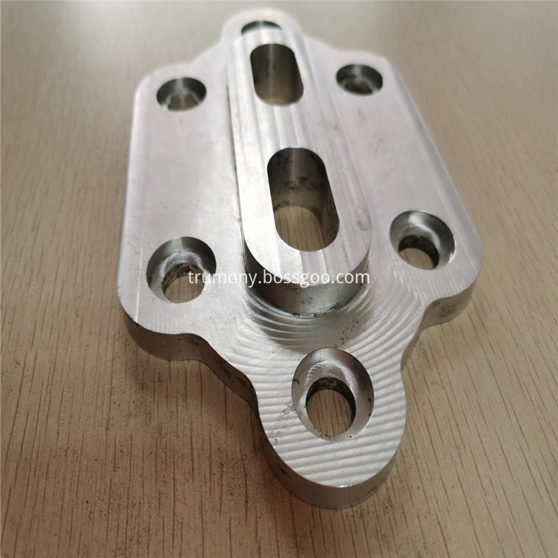
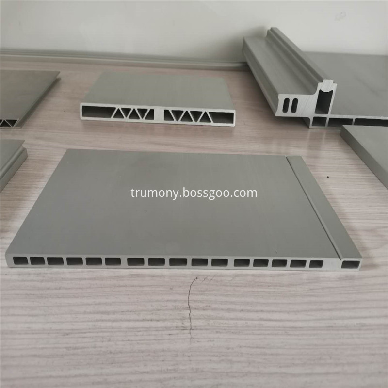
CNC Aluminum Sheet Or Spare Part is those parts processed by CNC machine.It takes longer production time sometimes.However,it also have good advantages.Such as The cutting and milling surface is smooth and burr - free, No need huge mould fees which can save your cost. Suitable for small quantity, small size or specification Aluminum Sheet or spare part. High milling precision of external dimension.Trumony is participate with specialized CNC machine supplier for aluminum sheet CNC production which gives fast delivery and consistant quality.Looking forward to your cooperation about CNC Aluminum Sheet Or Spare Part.
CNC Aluminum sheet, CNC aluminum alloy sheet, CNC Engraving and milling Aluminum alloy sheet Trumony Aluminum Limited , https://www.szaluminumcoil.com

Presupposition of compression techniques for auto-guard guards and their moulds