Application of mechanical equipment * HTAC radiant tube in gas-fired vacuum heat treatment furnace Luo Xiaochun, Liang Weimin, Jiang Manwen (Hunan Metallurgical Vocational and Technical College, Zhuzhou, Hunan 412000, China) Structure and properties. 3:A Article ID: 1003*5540 (2004) 02 China's heat treatment industry is a large energy-consuming machine industry, China's machinery manufacturing plant heat treatment accounted for 25% to 30% of the entire plant. National heat treatment industry has heat treatment furnace about 12X104 Taiwan, more than 90% of its electricity. The annual power consumption is approximately 100X108kWh. The average power consumption of heat treatment production in China is 700kWh/1, which is approximately twice that of Japan and Europe. The average power consumption of Japan's heat treatment production is about 323kWh/t, the average power consumption of heat treatment production in European industrial countries is 300~450kWh/t, the heat efficiency of heat treatment production in Japan is 49.8%, and the heat efficiency of heat treatment production in China is about 29%. . We know that electricity is a secondary energy source. The general fuel power generation efficiency is about 36%, and the thermal efficiency of electric energy is limited to about 80%. Therefore, the upper limit of the electric heating efficiency of fuel is about 29%. Natural gas energy is a primary energy source and natural gas is provided to users. Before purification, it is a cleaner energy source. In the current general technology, the upper limit of the thermal efficiency is about 50.5%, which is nearly twice as high as the thermal efficiency of the electrical energy. In recent years, many large-scale natural gas field structures have been discovered in China, with a total reserve of more than 1012m3. With the development of the western region and the international cooperation in the development of natural gas fields, natural gas production in China during the tenth five-year period can reach 645×108 m3 or more from 238×108 m3 in 1999, which will be exploited by China. Natural gas energy, changing the heat treatment of a single energy structure, and improving energy utilization to achieve comprehensive utilization of energy created the conditions. High-temperature air combustion technology (HTAC) is a brand-new combustion technology that has been popularized and applied in developed countries since the 1990s. High-temperature air combustion technology is achieved through small-sized peak ceramics (4mm to 5mm pitch) or ceramic balls (diameter 15~ 20mm) Regenerator, preheating the air and fuel temperature of the furnace to above 1000*C, up to 1250. Its oxygen concentration is lower than 15% (lowest to 3%~ 5%). Flue gas temperature is lower than 200*C The thermal efficiency of the furnace is as high as 80%. In this way, the combustion process takes place in a high-temperature, low-oxygen atmosphere, creating a flame character that is very different from traditional combustion. HTAC technology is applied to heat treatment furnaces and has many advantages such as high efficiency and energy saving, low pollution emission, and reduced combustion equipment size. In recent years, China has started to develop in this technical field, and it has achieved significant technical and economic benefits in industrial production. It is imperative to further develop and promote this advanced, energy-saving, and low-polluting advanced combustion technology during the period of the 15th. The development prospects are broad. Combining this technology with a radiant tube in a gas-fired vacuum heat-treating furnace, compared to the usual electric-heated vacuum heat-treating furnace, in addition to having all the advantages of an electric-heated vacuum furnace, it also has high productivity and high thermal efficiency; Operating costs; reduce maintenance and other multiple features. 1 Regenerative Radiant Tube (HTACRT) 1.1 Radiation Tube Heating Technology Radiating tube heating technology originally originated in Germany in 1936. The radiant tube heating device mainly consists of a pipe body, a burner, and a waste heat recovery device. The pipe body is a key component that radiates the heat energy released by the combustion of the fuel to the object to be heated. Because the inner surface is in direct contact with the combustion flame and high-temperature flue gas, the working environment is harsh, and it is easily burned and oxidized locally; if there is a large temperature difference along the length of the tube body, a large thermal stress will be generated and the combustion will occur. The impact of air flow will also produce a certain amount of vibration. Therefore, the pipe body should have good heat resistance, high thermal conductivity, strong high-temperature oxidation resistance, small thermal expansion coefficient, high structural strength, and good sealing performance. The burner is the core of the radiant tube heating device. It controls the power, temperature distribution, thermal efficiency and service life of the radiant tube. The common forms of traditional radiant tube burners are the parallel burners and the swirl burners, both of which use room temperature or Pre Luo Xiaochun, etc.: Application of HTAC radiant tubes in gas-fired vacuum heat treatment furnaces This combustion will produce local high-temperature areas. The peak temperature of combustion is higher, and there is a large temperature difference along the length of the radiant tube, causing localized high-temperature burning and oxidation corrosion on the inner surface of the radiant tube. If the combustion air is preheated, the NOx emission concentration formed by combustion will also increase significantly. The waste heat recovery device is an important component to improve the thermal efficiency of the radiant tube heating device. Early use of the radiant tube heating device, because there is no smoke heat recovery device, exhaust heat loss is large, its thermal efficiency is less than 50%. Later, in order to improve the thermal efficiency of the radiant tube heating device, waste heat is set at the exhaust end of the radiant tube. The recovery device recovers the excess heat of the exhaust gas to preheat the combustion air. However, because the waste heat recovery device adopts an ordinary partition type structure, the heat recovery effect is not very satisfactory, and the air preheating temperature is only about 30% of the waste heat recovery rate of 200 to 300 flue gases. The thermal efficiency of traditional gas radiant tube heating devices is difficult to exceed 75%. With the continuous development of refractory materials, continuous improvement of product quality, and continuous improvement of heat treatment technology, the United States, Japan and Europe and other countries widely use this indirect heating technology. In recent decades, this technology has gradually been applied in China's metallurgy, machinery, light industry and other industries. 1.2 Introduction to HTACRT The HTACRT uses high-temperature air combustion technology and utilizes a peak-pot ceramic regenerative heat exchange device. A regenerator chamber is installed at both ends of the radiant tube outlet. The highest frequency is achieved through four-way valve switching. Extremely high-temperature flue gas waste heat recovery, the implementation of high temperature preheating combustion air. The device has the characteristics of large heat storage, fast heat exchange, good structural strength, high temperature and pressure resistance, resistance to oxidation and corrosion, low resistance loss, and economical durability. The main component of its material is alumina. Due to its porous structure, the heat exchanger has a very high specific surface area. The honeycomb channel is straight, and the pressure loss is small, so it is not easy to cause dust blocking. Because of the high-speed heat storage and heat release of the heat accumulator, the switching time can be set to 20~30s. With this device, the temperature above 1000*C can be achieved. The flue gas is reduced below 200 *C, and the ambient air is preheated to near the high-temperature flue gas temperature (typically the difference is only 50~150*C). The thermal efficiency of the device can reach more than 80%. Since this type of thermal storage body has a very high heat transfer specific surface area, the amount of heat storage body requirements is greatly reduced, so that the addition of the heat storage body has little effect on the volume of the radiant tube. At the same time, the use of combustion flue gas backflow and other measures can control the oxygen concentration in the combustion zone to less than 15% or even lower. Therefore, the combustion flame has a multiplied volume, a reduced brightness, a lighter color, a lower peak temperature, a uniform temperature field distribution, a stable combustion range, low combustion noise, and no local high-temperature and high-oxygen area of ​​the conventional flame; As the temperature decreases, thermal NOx formed by combustion is greatly reduced. 1.2.1 The structure and working principle of the HTACRT The length of the middle section can form a double U-shaped radiant tube. The structure of the W-type regenerative radiant tube is as shown. Mainly by the regenerator, burner, radiant tube, reversing valve composition. After the cold air is heated by the heat storage body of the burner on the A side, it is combusted with the fuel; the hot flue gas in the radiant tube heats the heat storage body of the burner on the B side and is discharged from the flue. After a set period of time, the direction of flow in the radiant tube is changed. Cold air flows into the B-side burner, and the flue gas is discharged from the A-side burner. The cold air and the hot flue gas alternately flow through the regenerators on burners A and B on both sides to exchange heat through the regenerator. The air can be heated to a temperature close to the hearth, and the flue gas temperature can be reduced to below 200 C to achieve the flue gas. Heat limit recovery. The change of the flow direction of the air and the flue gas, and the on-off of the burner fuel gas are achieved through special valves and control systems. Characteristics of schematic diagram of structure of W-radiation tube Regenerative high-temperature air combustion technology applied to the gas radiant tube heating device can make the surface temperature distribution of the radiation tube more uniform, the heating capacity and the heating quality are improved, and the thermal efficiency is greatly improved. With longer service life, pollutant emissions are significantly reduced. 1.2.21 Radiating tube surface temperature distribution The uniformity of the surface temperature distribution of the gas radiant tube is a very important technical performance index. It affects the heating capacity, the heating quality, and the service life of the radiant tube. Radiating tube surface temperature distribution uniformity can be characterized by its temperature non-uniform coefficient. The smaller the temperature non-uniform coefficient is, the more uniform the temperature distribution is. In engineering, the uniformity of the surface temperature distribution is usually judged by the deviation of the temperature distribution of the radiation tube. The difference of the temperature distribution of the traditional U-shaped radiant tube is usually *20~*50C. The HTAC technology is used. Due to the uniformity of the temperature distribution of the high temperature air combustion flame and the high frequency switching between the preheated air and the high temperature smoke, the radiant tube is The flow of air is frequently commutated. The temperature distribution of the wall of the radiant tube is more uniform. The difference in the temperature distribution of the radiant tube can reduce the difference in surface temperature distribution to about *10C. 1.2.22 Thermal efficiency The thermal efficiency of the gas radiant tube is an important technical performance indicator of the radiant tube. Its calculation formula is: Quantity/JQa is the amount of heat introduced by the preheated air AJ; Qf is the amount of heat emitted by the flue gas/kJ. Radiant tube air preheating temperature 300 using HTACRT air preheating temperature to 850 * C, the two using 1.02 excess air coefficient, by calculation, the general gas radiant tube heating device thermal efficiency of only 62.21%, while the thermal efficiency of HTACRT is 85.30%, the thermal efficiency is increased by 23.09%. The excess air coefficient required for high-temperature air combustion is usually smaller than normal air combustion. For example, high-temperature air combustion requires only an excess air ratio of 1.02, and ordinary air combustion may be needed at room temperature. 1. An even higher excess air factor. If the furnace temperature is higher and the effect of the excess air factor on the thermal efficiency is taken into account, the thermal efficiency will be even greater. 1.2.23 The service life of the radiant tube The service life of the radiant tube is affected by many factors. The surface temperature distribution of the gas radiant tube is the main factor affecting the service life of the radiant tube. If there is a large temperature difference in the surface temperature of the radiant tube, the stress distortion or local overheating caused by the temperature difference will cause damage to the radiant tube and also affect the uneven output power of the radiant tube surface. For example, if the output power of the radiant tube is double the rated output power, the service life of the radiant tube will be shortened to about 1/10. With HTAC technology, this problem can be well solved. In addition, the use of a low excess air ratio combustion and backflow of combustion products reduces the oxidizing properties of the atmosphere within the radiant tube, which is also very advantageous for extending the service life of the radiant tube. Emissions. This is because: (1) the peak temperature of the high-temperature air combustion flame is reduced, the temperature field is evenly distributed, and the oxygen concentration of the combustion atmosphere is reduced by the low excess air coefficient combustion and the combustion product recirculation, and the formation of thermal NOx is suppressed; (2 ) High-speed air flow in the radiant tube shortens the residence time of the high-temperature flue gas in the furnace and also helps to reduce the generation of NOx. (3) High-temperature air combustion can greatly save fuel, and CO2 in the combustion products is significantly reduced, thus reducing greenhouses. Gas emissions. 2 Regenerator Radiant Tube (HTACT) Gas High Temperature Air Combustion Technology (HTACT) is a high-efficiency, energy-saving and environment-friendly advanced combustion technology developed rapidly in the 1990s. Compared with traditional combustion technology, high-temperature air combustion technology through the regenerative flue gas furnace temperature uniformity 5 * C, its combustion thermal efficiency can be as high as 80%. High-temperature air combustion technology can save energy by more than 60% through high-temperature air burners and recovery devices, which can reduce CO2 emissions by more than 60%. At the same time, high-temperature air combustion technology achieves combustion in the oxygen-lean region, greatly reducing NOx emissions, up to 40X106 orders of magnitude (40~ 50mg/m3), which is 15~1/20 of conventional combustion technology. In addition, high-temperature air combustion noise is low, which reduces noise pollution. High-temperature air combustion technology has developed several high-temperature air burners (regenerative burner heating system), Japan, the United States, Europe have been used for production, the technology has developed and applied mature, its technical and economic benefits are significant. In recent years, several regenerative burners and combustion device systems have been developed in this technology field in China, and they have been successfully applied in industrial production. The technology has huge economic benefits and superior environmental performance. 21 Structure and main technical parameters Regenerative radiant tube vacuum heat treatment furnace structure is shown. Natural gas low calorific value gas radiant tube size /mm radiant tube diameter 0/mm 22 Main features 1. Like electrothermal vacuum heat treatment furnace, annealing, quenching, tempering and other heat treatment can be performed. 2 The furnace has high thermal efficiency, and the fuel cost can be reduced by 2/3 compared with the electric type. The HTAC technology can realize double preheating of air and gas, and the air and gas double preheating can maximize heat recovery when burning low calorific value gas. The flue gas can be completely discharged through the air regenerator and the gas regenerator. The furnace does not need auxiliary flue and chimney to make the furnace waste heat recover and make the air reach the smoke. The structure and arrangement of 95% of the degree are simplified. Air d and gas dual preheating bring a series of advantages. The combustion temperature is greatly increased, thus expanding the scope of application of the fuel, the strong flame stability. Under the condition that air and gas can be double preheated to 95% of the flue gas temperature, the air and gas temperatures are above the ignition point of the gas, and the combustion reaction occurs spontaneously. The air and gas concentrations are no longer the conditions for stable combustion, any concentration Can guarantee stable combustion. Therefore, low-oxygen diffusion combustion can be realized. The exhaust temperature of the system is lower than 200, which is close to the limit value of waste heat recovery. The thermal efficiency of the furnace is as high as 80%. The air and gas preheating temperatures are close to the furnace temperature, thereby greatly improving the temperature uniformity in the furnace. The energy required for heating the furnace is calculated based on the thermal efficiency of the burner, the heating temperature, and the measured value of the furnace heat retention, and then compared with the electric heating operation cost. The regenerative burner unit consumes 175m3/burner gas, and the electric heating unit consumes 167kW/h, which makes it easy to calculate the operating costs based on energy prices in different regions. The calculated energy consumption of the regenerative burner is only 38% of that of the electric furnace. The calculation conditions are as follows: (1) furnace temperature: 1050°; 2) burner thermal efficiency: 85%; (3) heating efficiency: 100%; (4) Furnace heating capacity: 70 kW (burning amount of burner 41 kW X 2) (5) Holding heat: 33 kW (burning amount of burner 39 kW) (6) Heating time: 105 min, Holding time: (7) Number of taps: 150 kiln/month. 3. As with the electric vacuum heat treatment furnace, HTACRT gas-fired vacuum heat treatment furnace has excellent environmental characteristics, NOx emissions are very low, up to 40X106 magnitude (40 ~ 50mg/m3), for the traditional combustion technology V15 ~ 1/20; C2 emissions can be reduced by more than 60%; in addition, high-combustion gas combustion technology has low noise and noise pollution. 3 Conclusion Gas-fired vacuum heat treatment furnace is a kind of high-efficiency (heat efficiency up to 80%) high-quality, energy-saving (above 60%) materials and materials developed by European and American countries in the late 1980s under the impact of the oil crisis and promoted by high-temperature air combustion technology. The new type of heat treatment equipment with environmental protection (NOx, C2, and greatly reduced noise) type, due to the advanced technology and the great potential of energy saving and material saving, the technical and economic benefits are remarkable. At the same time, the technology has excellent environmental protection characteristics and meets the requirements of green heat treatment and sustainable development. The development strategy therefore has broad prospects for development.
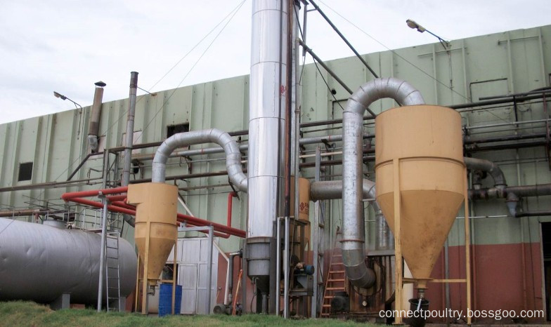
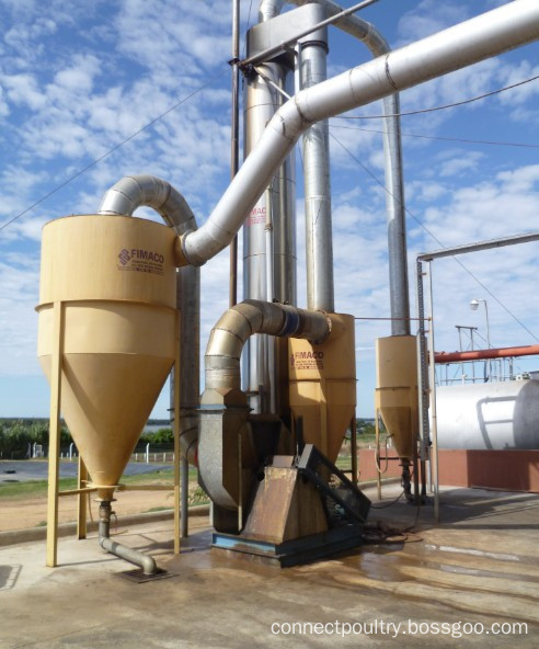
The raw material of poultry and animal wastes after cooking in batch cooker and cooked meal dried in Dryer, it generates any odor from the whole process, when the odor released from batch cooker and dryer, first it goes into Dust collector which to collect the meal which release with odor in catcher, and then the odor go to condensor which most of odor condensed , and the odor which not condensed goes to chemical washing tower , during these processing, the odor complete remove and reach to the air releasing standard. Connect Odor Treatment system help you get environmental protect solution for your rendering plant. No any odor release from your plant.
4. It is easy to remove pipe scale, not need to stop the working of refrigeration system.
Odor System, Deodorizing System, Deodorize Equipment Connect Group For Poultry Project , https://www.connectpoultry.com
First: Water-cooled condenser
Functions:
Water-cooled condenser take water as cooling medium to remove condensation heat by raising temperature of water.
Feathers:
1. There is no strick requirement on water quality,generally water can be used as cooling water. The cooling water flow fast
2. It is easy to remove pipe scale, not need to stop the working of refrigeration system.
Second: Open Model condenser
Functions: Water-cooled condenser take water as cooling medium to remove condensation heat by raising temperature of water.
Feathers:
3. There is no strick requirement on water quality,generally water can be used as cooling water. The cooling water flow fast


Application of HTAC Radiation Tube in Gas Vacuum Heat Treatment Furnace
Application of HTAC Radiation Tube in Gas Vacuum Heat Treatment Furnace
Core Tip: Mechanical Equipment * Application of HTAC Radiant Tube in Gas-fired Vacuum Heat Treatment Furnace Luo Xiaochun, Liang Weimin, Jiang Manwen (Hunan Metallurgical Vocational College, Zhuzhou, Hunan 412000, China) Structure and properties. 3: A Article ID: 1003*5540 (2004) 02 China's Heat Treatment Line