The transmission error of the machine tool refers to the difference between the actual displacement of the output shaft and the theoretical displacement under the condition that the input shaft of the machine drive chain is driven completely accurately and rigidly. The drive chain for the composite movement required to form the surface of the workpiece on the machine tool – the end-to-end actuators of the “internal connection†drive chain must always maintain a strict motion relationship that meets the specified requirements. The transmission accuracy of the transmission chain refers to the accuracy of the transmission motion, which can be measured by the transmission error. Due to the actual transmission chain error of the machine tool, there is an error in the forming motion path of the workpiece surface, which is finally reflected on the workpiece to be processed, which causes the shape error of the forming surface. Since the machine tool transmission chain is mainly composed of gear pair, worm gear pair, thread pair, etc., the transmission chain error mainly comes from the machining precision and installation accuracy of these transmission components. From a kinematic point of view, all factors that cause the instantaneous gear ratio to deviate from a given transmission requirement are sources of drive chain error. The measurement of machine tool transmission error is the premise of effective compensation for transmission error. Therefore, the precision measurement of machine tool transmission error has always been an important research topic of mechanical transmission technology. The basic measurement method of machine tool transmission error is to install the sensor in the relevant part of the machine tool. By using the measuring instrument of machine, light and electric principle and applying the error evaluation theory, the error of each link of the machine tool transmission system is measured, analyzed and adjusted. The cause of the error and the law of change. Sensor selection Correct and reasonable selection and installation of the sensor according to the motion characteristics of the end components of the transmission chain are necessary conditions for accurately measuring the motion accuracy of the transmission chain. According to the working principle, the commonly used sensors for machine tool transmission error measurement can be divided into the following categories: (1) Grating sensor The biggest advantage of the grating sensor is that the signal processing method is simple, easy to use, and the measurement accuracy is high (the accuracy of the grating sensor manufactured by famous foreign manufacturers such as Heidenhain of Germany and Fagor of Spain can reach 1μm/m); the disadvantage is that the grating ruler is more expensive, The working environment is relatively high, and the linear expansion coefficient of the glass grating is inconsistent with the machine tool, which is easy to cause measurement error. (2) Laser sensor Laser sensors (including single-frequency and dual-frequency lasers) have high measurement accuracy, but the measurement cost is also high. They are sensitive to changes in environmental conditions (such as temperature, airflow, vibration, etc.). Measures must be taken when using them at the production site. Measurement stability and reliability. (3) Magnetic grid sensor The magnetic scale can be divided into two types: linear (effective measuring length 3m) and strip shape (effective measuring length up to 30m), which has the advantages of low manufacturing cost, convenient installation and use, and the linear expansion coefficient is the same as that of the machine tool; The measurement accuracy is lower than that of the grating scale, and since the magnetic signal strength is continuously weakened with the use time, it is necessary to re-record the magnet, which is inconvenient for use. (4) Inductive synchronizer The advantages of the inductive synchronizer are low manufacturing cost, convenient installation and use, and low requirements on working environment conditions; the disadvantage is that the signal processing method is complicated, and the measurement accuracy is limited by the measurement method (the measurement accuracy of the conventional measurement method is about 2 to 5 μm) . Some applications of several types of machine tool transmission error measurement sensors are currently used. Some applications of several types of commonly used sensors Sensor Type - Application Unit - Measurement Resolution: Line Displacement (μm) - Measurement Resolution: Angular Displacement (Angular Seconds) Grating sensor - University of Tokyo, Hanjiang Machine Tool Plant Laser sensor - single frequency laser: Beijing Machine Tool Institute, University of Tokyo Laser Sensor - Dual Frequency Laser: Chengdu Tool Research Institute, Shanghai Machine Tool Plant Magnetic Grid Sensor - University of Tokyo, Chongqing University, Huazhong University of Science and Technology, Hanjiang Machine Tool Plant, University of Wisconsin, USA Induction Synchronizer-Shandong University of Technology, Hanchuan Machine Tool Plant Sensors can be divided into analog and digital types according to different signal output methods. Digital sensors can be divided into incremental, absolute and signal modulation. In the computer test system, the output signal of the analog sensor needs to be digitized by analog-to-digital converter (A/D), and the cost of A/D conversion is high at high resolution, and the small analog signal is solved. The anti-interference problem of microvolts is also quite difficult. In digital sensors, absolute encoders can output parallel digital signals without the need for A/D conversion, making it easy to interface with a computer. However, with the improvement of measurement accuracy, the cost of absolute encoders is also higher and higher, even higher than the cost of high-precision A/D conversion, so it is difficult to be accepted in many practical applications. Incremental sensors and signal-modulated sensors have lower manufacturing costs and stronger anti-interference ability, and can be used to greatly improve the resolution by subdividing without changing the engraving density of the encoder. Therefore, in the accuracy measurement of the transmission chain. These two types of sensors are the most used. Common incremental sensors include grating incremental encoders, magnetic grid sensors, capacitive encoders, etc.; signal modulation sensors are mainly inductive synchronizers, laser interferometers, seismographs, resolvers, and the like. Dynamic measurement method of machine tool transmission error The basic measurement principle of transmission error: Let θ1 and θ2 be the displacements of the input and output shafts (angular displacement or linear displacement) respectively. The theoretical transmission ratio between input and output is i. If θ1 is used as the reference, the actual displacement of the output shaft. The difference from the theoretical displacement is the transmission chain error δ, that is, δ=θ2-θ1/i. According to the measurement methods of the displacement signals θ1 and θ2, the transmission error measurement method can be divided into the phase measurement method and the counting method. Big class. 1 machine tool transmission error ratio phase measurement method The phase relationship between the output signals θ1, θ2 of the two sensors reflects the transmission error of the drive train. When the transmission error TE=0, that is, the transmission ratio is constant, a constant phase relationship is maintained between θ1 and θ2; when the transmission ratio i changes, the phase relationship between θ1 and θ2 also changes. The phase measurement method indirectly measures the transmission error TE by measuring the phase relationship between θ1 and θ2. With the development of digital technology and computer technology, the phase measurement method has experienced the analog phase to phase → digital phase ratio → computer digital ratio The development process of the phase. (1) Analog phase method The commonly used trigger phase meter uses the analog phase comparison method. The principle of analog phase comparison: after the two signals are divided, they become the same frequency signal and enter the specific phase meter. The time difference Δt between them depends on the phase difference δ(t) between θ1 and θ2. After being identified by the bistable flip-flop, Δt is converted into an analog quantity Δu corresponding to the duty ratio of the phase rectangular wave, and the change of the duty ratio reflects the transmission error of the transmission chain. The analog phase measurement system has the following problems: 1δ(t) is a periodic function with a period of 2π and a certain law. Let f be the phase change frequency and ω=2πf be the angular frequency, then δ(t)=δ( Ωt). When the two signals are in phase, the phase measurement is a repeated measurement with a period of 1/f. From the condition 0 ≤ δ(ωt) ≤ 2π, Δu has a linear relationship with δ(t). Since δ(ωt) changes periodically, it is required that the time constant τ of the analog recording head is smaller than the period of the measured change phase difference, that is, τ ≤ 1/f, otherwise, when an accurate reading has not been obtained in the previous phase change period, The latter cycle has begun to repeat, so that the phase difference change cannot be recorded in real time. Therefore, the dynamic measurement performance of the analog phase comparison method is poor, and it cannot meet the dynamic measurement requirements of real-time analysis processing. 2 The measurement resolution and the measurement range are mutually constrained. If the resolution is increased, the range is reduced. To do this, the range selection circuit needs to be configured, and the phase difference of the measured signal must be less than 360°. 3 It is required to enter the same frequency of the two signals than the phase meter, that is, only the same frequency ratio phase can be performed. Therefore, the frequency division/multiplier of the two signals must meet the transmission ratio change requirement, the circuit structure is complex, and the anti-interference ability is poor. The range is small. (2) Digital ratio method The digital phase is implemented by logic gates and counters, and the phase difference is directly output in digital form. The phase comparison principle: two co-frequency signals θ1 and θ2 are amplified and shaped to obtain two sets of pulse signals u1 and u2, which respectively control the opening and closing of the counter through a logic gate circuit. The counting result of the counter is the time interval Δt between θ1 and θ2, which is proportional to the phase difference δ(t). Let the phase of the phase signal be T, then δ(t)=2πΔt/T. The main features of the digital ratio phase measurement method are: 1 Since the value of Δt depends not only on the phase difference δ(t) of the two signals, but also on the frequencies of the two signals. Therefore, in order to obtain higher-accuracy measurement results, it is necessary to ensure high accuracy of both phase-phase pulse signals and clock signals. In a phase-to-phase period T, any factor that causes a change in the frequency of the phase signal will affect the measurement. 2 Although the digital ratio compensates for some of the shortcomings of the analog phase, the measurement stability and reliability are improved, but it can only be applied to the same frequency ratio phase. (3) Microcomputer subdivision ratio phase method Since the 1980s, the computerization of test instruments has become an important development trend of measurement technology. In the machine tool transmission error measurement, the microcomputer subdivision ratio phase method has begun to be widely used. The microcomputer subdivision ratio phase method is a microcomputer application of the digital phase comparison method. Because the computer has powerful logic, numerical calculation function and control function, it is easy to realize the high-frequency clock subdivision, phase comparison and output of the two signals, so the peripheral circuit is relatively simple to manufacture. The transmission error is δ(t)=2πNt/N. In the phase comparison process, the high frequency pulse φ is no longer generated by the external oscillating circuit, but directly uses the internal clock CP of the computer; the counting of the pulse CP no longer uses the logic gate counter. And use a programmable timer/counter in the computer. The microcomputer subdivision ratio phase measurement method has the following advantages: 1 The two-way phase-to-phase signal does not need the same frequency (ie, the transmission ratio of the tested transmission chain can be any value), and the transmission ratio is a constant in the calculation of the transmission chain error. The phase-to-phase phase difference can be any value, and the phase difference must be less than 360°. 3 The integration of clock subdivision and phase comparison is realized, which greatly simplifies the hardware interface line. Since the number of divisions of the programmable counter can be controlled by computer software, the sampling frequency can be easily adjusted to accommodate the measurement of the transmission chain error at different speeds. 4 system subdivision accuracy and measurement accuracy is high, easy to form an intelligent, multi-functional measurement system. 2 machine tool transmission error counting method The analog phase and the digital phase are both in the same frequency ratio phase. In order to obtain the same frequency ratio phase signal, the gear ratio must be first divided. To ensure that the 2π phase inversion does not occur in each error range, the range division is also required. Since the crossover reduces the measurement resolution, it is necessary to multiply the frequency before the frequency division, which makes the measurement system more complicated. In addition, measurements cannot be made for non-integer gear ratios due to the inability to divide the frequency. The digital counting measurement method adopts the non-same frequency ratio phase, so it is not necessary to divide the two pulse signals, and the number relationship between the output pulses of the two sensors can be directly used to calculate the computer bed transmission error. (1) Direct counting measurement The principle of direct counting measurement method: set the number of output signals per revolution of the input and output shaft sensors to λ1 and λ2, respectively, and select the output axis θ2 as the reference axis, and the sampling interval T is equal to the period of the θ2 pulse signal or an integral multiple thereof. According to the definition of the transmission error, the transmission error at the jth sampling is: δ(j)=[N1(tj)-N2(tj)(iλ1/λ2)]2π/λ1. Since θ1 and θ2 are time-discrete pulse trains, the count N1(tj) of the θ1 pulse in the sampling time interval (N2 θ2 pulses) varies with time during measurement, and is usually a non-integer. Thus, the error Δ2π/λ1 caused by the fractional part Δ is ignored. In addition, the (iλ1/λ2) of the actual transmission system is not necessarily always an integer, that is, the frequency of the pulse θ1 is not necessarily an integer multiple of θ2. If the N1 theory is regarded as an integer processing, a theoretical error is caused, thereby limiting the application range thereof. (2) Microcomputer subdivision counting measurement method The measurement steps of the microcomputer subdivision counting measurement method are as follows: 1 the previous θ2 pulse is used as the door opening signal, the latter θ2 pulse is used as the closing signal, and the counter counts the number of pulses θ1 of the θ1; 2 the clock sequence θ1 is performed by the clock pulse CP. Interpolation subdivision, counting the fractional period count value TΔ and the integer period count value T2 of the θ1 pulse signal respectively; 3 calculating the transmission error: δ(t)=(N0+TΔ/T2-iλ1/λ2)2π/λ1. The microcomputer subdivision counting measurement method has the following advantages: 1 can effectively reduce the measurement error Δ; 2 can fully utilize the internal resources of the computer and software control to simplify the external hardware circuit; 3 integrate measurement sampling, data processing and result analysis to achieve Intelligent measurement.
Parallel Shaft Reducer:
Demonstration:
Total centre diameter is 1500 mm and adopting the double-stage cylinder and arc antifriction bearing gear reducer ZHLR-1504.
Major Technical Data:
The relative error between actual transmission of the reducer and the nominal transmission ratio is less than 4%.
Factory Equipments
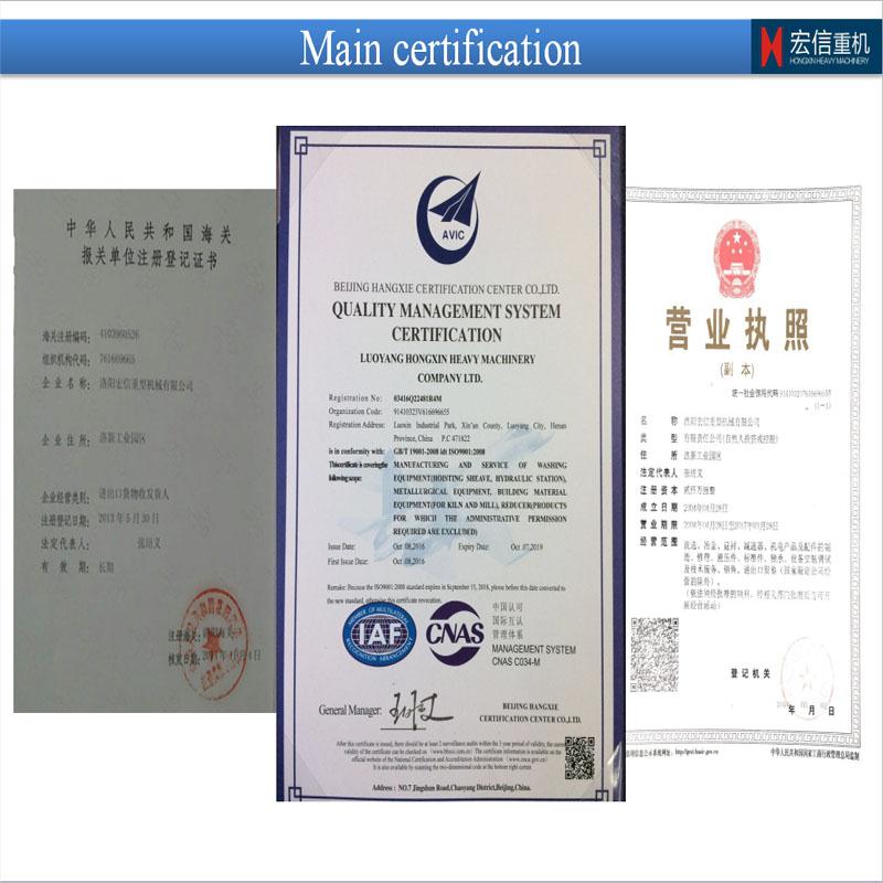
Luoyang Hong Xin Heavy Co., LTD. is located in Luoyang Xin'an Industrial Park, Luoyang Hongxin Heavy Machinery Co., Ltd is an enterprise featured with industrial designing, processing and manufacturing, which is qualified for import-export trade. Covering an area of 15,000 square meters and holding an annual production value of 80 million RMB, the company of 20 million RMB registered capital has total 100 staff members, among which there are 20 engineering technicians owning senior and medium professional titles and 40 intermediate and senior technicians capable of product designing and developing.
Hongxin is dedicated to produce reducers, hoists, crushers, Ball Grinding Mills and the equipments of screening, coal washing, metallurgy and cement, and replacement parts. Meanwhile, we provide the perform maintenance service for various series of equipments. There are 52 large-scale equipments applied into the manufacturing process, such as T200 CNC floor boring and milling machine, YK 73125 CNC molding gear grinding machine, YK322B CNC molding gear grinding machine, Y3200 gear hobbing machine, Y1600 CNC gear sharper, 4m vertical lathe, 6.3m CNC vertical lathe, T110 CNC boring machine, and 52 middle-sized productive and assistive equipments, which integrate strong manufacturing and processing capability with complete managing system of production and technology, quality management system and comprehensive testing measures
Contact us
Parallel Shaft Reducer,Parallel Shaft Helical Reducer,Parallel Shaft Gearbox Speed Reducer,Hollow Shaft Parallel Reducer Luoyang Hongxin Heavy Machinery CO., TLD. , http://www.hxreducer.com


Analysis of Measuring Method of Machine Tool Transmission Error